نصب و راه اندازی به سادگی
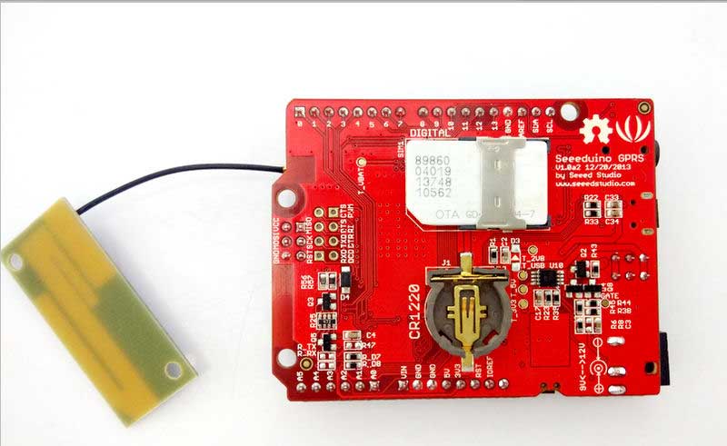
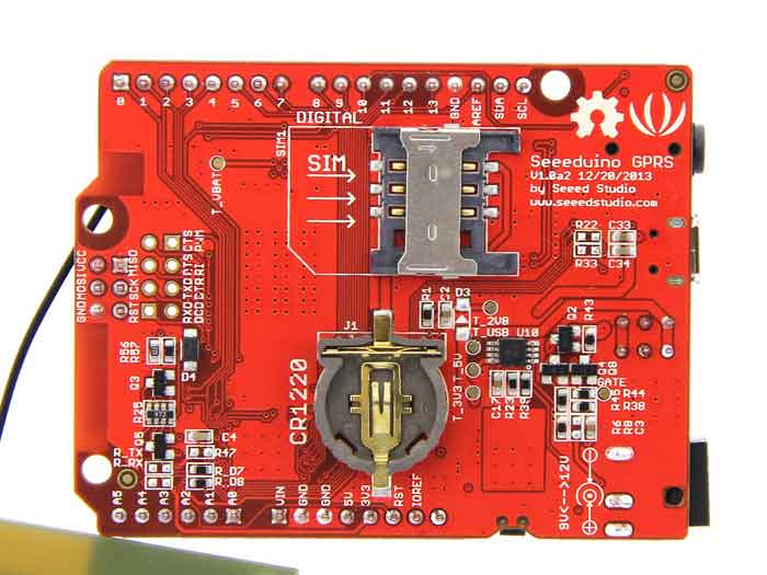
سیم کارت را بر اساس الگویی که پشت برد ترسیم شده وارد کنید و کابل میکرو یو اس بی را به برد و کامپیوتر متصل کرده، برنامه آردوینو را نصب کنید و کام پورت را در برنامه تعریف کرده و برد آردوینو را ARDUINO LEONARDO تعریف کنید و سپس برنامه زیر را آپلود کنید و پنجره سریال مانیتور را باز کرده و مراحل شروع برنامه را رصد کنید.
[code lang=”arduino”]
<;">#include <gprs.h>
#include <SoftwareSerial.h>
GPRS gprs;
void setup() {
Serial.begin(9600);
Serial.println("GPRS – Send SMS Test …");
gprs.preInit();
delay(1000);
while(0 != gprs.init()) {
delay(1000);
Serial.print("init error\r\n");
}
Serial.println("Init success, start to send SMS message…");
gprs.sendSMS("0098917*******","test seeeduino gprs imei 8629500248*****"); //define phone number and text
//gprs.callUp("0098917*******");
}
void loop() {
//nothing to do
}
<[/code]
DESCRIPTION
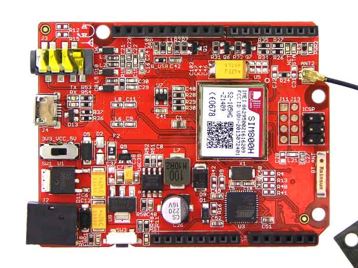
Seeeduino GPRS is a IoT panel, you can connect to the internet through GPRS wireless network with it. Making/answering voice calls and sending/receiving SMS messages are also supported. Meanwhile, Seeeduino GPRS supports FM radio function and bluetooth communication. Seeeduino GPRS is base on Atmage32U4 and SIM800H. Atmage32U4 is a microcontroller and it is compatible with Arduino. SIM800H support Quad-band 850/900/1800/1900MHz, it can transmit Voice, SMS and data information with low power consumption. SIM800H also brings some extra features like for example Bluetooth and FM radio. It is designed with power saving technique so that the current consumption is as low as 0.1mA in sleep mode.
SPECIFICATION
- • Compatible with standard Arduino leonardo
- • Quad-Band 850/900/1800/1900MHz
- • Headset jack
- • Convenient external SIM card holder
- • Control via AT commands
- • Support Bluetooth
- • Support FM
DOCUMENTS
Please visit our wiki page for more info about this product. It will be appreciated if you can help us improve the documents, add more demo code or tutorials. For technical support, please post your questions to our forum.
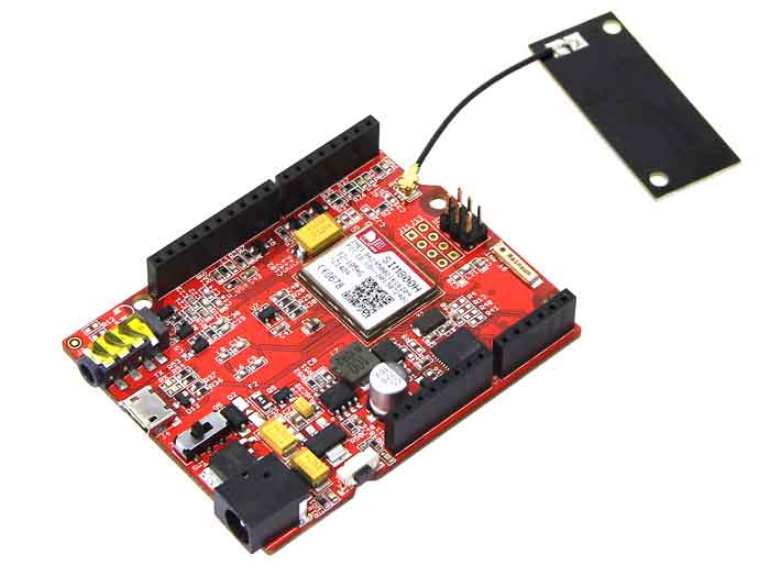
Specification
- Compatible with standard Arduino Leonardo
- Quad-Band 850/900/1800/1900MHz
- Headset jack
- Convenient external SIM card holder
- Control via AT commands
- Supports Bluetooth
- Supports FM Radio
- Current < 2A
- Arduino Leonardob Bootloader
Interface Function
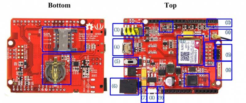
- ⑴:SIM Card Interface
- ⑵:Battery CR1220
- ⑶:Headset Interface :3.5mm headphones
- ⑷:Micro USB:Port used to connect the board to your PC for programming
- ⑸:Power Switch:Slide switch used to change the logic level and power output of the board to either 5V or 3.3V. Nowadays many new and great sensors are being develop to work with 3.3V, with other duino boards you would need to place a logic level converter between the board and these sensor(s), with the Seeeduino GPRS board all you have to do is slide the switch!
- ⑹:DC Jack:The DC power jack allows your Seeeduino GPRS board to be powered from a wall adapter so that you can supply more power to your project if needed, for example when using DC motors or other high power devices. The DC input can be 9V-12V. As peak current is 2A when model is power on, DC Power is your batter choice then USB power.
- ⑺:Power LED : it will light when power is normal
- ⑻:Reset button :it can reset SIM800h and MCU
- ⑼:Reset indicator LED
- ⑽:MCU: The ATMEGA32U4-MUR chip
- ⑾:GPRS Model: SIM800h
- ⑿:Breakout for SIM800h :You can edbug sim800h by this interface.
- ⒀:LEDs indicator
- PWR2:SIM800 Power Indication
- STA:Operating Status Indication
- NET:Network status
Status SIM800H behavior Off SIM800H is not running 64ms on/800ms off SIM800H not registered the netwark 64ms on/3000ms off SIM800H registered the netwark 64ms on/300ms off SIM800H communication is established - ⒁:GPRS antenna
- ⒂:ICSP interface:This is the ICSP connection for the ATMEGA32U4-MUR, it is located in the standard ICSP/SPI position for Arduino Uno, Due, Mega, and Leonardo compatible hardware (e.g. shields) that may use this connector. The SPI pins in this port: MISO, SCK, and MOSI, are also connected to digital pins 12, 13, and 11 respectively just like those of the Arduino Leonardo.
- ⒃:Bluetooth antenna
- ⒄:The “L” LED is connected to digital pin 13, it can be used a “status” LED in your projects,you can status by programming
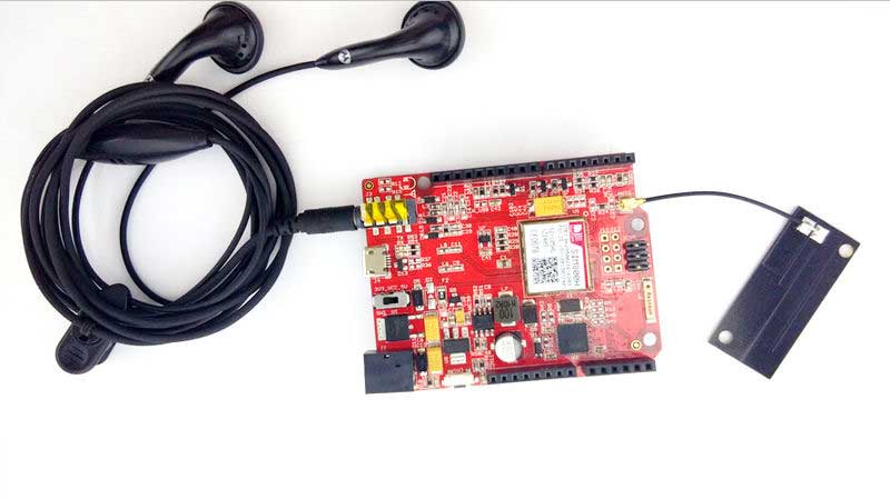
Hardware Connection
Note: To test the GPRS function, a headphone and a SIM card would be required.
Getting Started
Below is the introduction of how to play with a Seeeduino GPRS module. Please take the example sketch in the library as reference.
GPRS Function
Seeeduino GPRS offers the function of a mobile phone such as making/receiving voice calls, sending/receiving SMSes, make a TCP connection etc. You can find them in examples. Here is a brief introduction.
To make a Call
Open the example sketch GPRS_CallUp in libraries/Seeeduino_GPRS/example/GPRS_CallUp/, replace the phone number in callUp function, then compile the sketch and upload it to your board. Seeeduino GPRS will call the number specified in the code.
#include <gprs.h>
#include <SoftwareSerial.h>

GPRS gprs;

void setup() {
    Serial.begin(9600);
    Serial.println("GPRS - Call up Test...");
    gprs.preInit();//power on SIM800
    delay(1000);
    while(0 != gprs.init()) { //gprs init
        delay(1000);
        Serial.print("init error\r\n");
    }
    Serial.println("Init success, start to call...");
    gprs.callUp("150****9566");
}

void loop() {
    //nothing to do
}
To send an SMS
Just like calling, an SMS can be sent with Seeeduino GPRS. Open the example sketch GPRS_SendSMS in libraries/Seeeduino_GPRS/example/GPRS_SendSMS/, and replace the phone number and message in sendSMS function, then compile the sketch and upload it to your board. Seeeduino GPRS will send the message to the number specified in the code.
#include <gprs.h>
#include <SoftwareSerial.h>

GPRS gprs;

void setup() {
    Serial.begin(9600);
    Serial.println("GPRS - Send SMS Test ...");
    gprs.preInit();
    delay(1000);
    while(0 != gprs.init()) {
        delay(1000);
        Serial.print("init error\r\n");
    }
    Serial.println("Init success, start to send SMS message...");
    gprs.sendSMS("130****3364","hello,world"); //define phone number and text
}

void loop() {
    //nothing to do
}
To answer a Call & read an SMS
If someone calls or send a message to you, Seeeduino GPRS can also answer the call or read the message out. Open the example sketch GPRS_LoopHandle in libraries/Seeeduino_GPRS/example/GPRS_LoopHandle/, then compile the sketch and upload it to your board, the Seeeduino GPRS will poll to check if there is an incoming call or SMS. If there is an incoming call, Seeeduino GPRS will answer the call automatically. If there is an incoming SMS, Seeeduino GPRS will show the message in Serial Monitor.
#include <gprs.h>
#include <SoftwareSerial.h>
#include <stdio.h>

char gprsBuffer[64];
int i = 0;
char *s = NULL;
int inComing = 0;

GPRS gprs;

void setup() {
    Serial.begin(9600);
    Serial.println("GPRS - LoopHandle Test...");
    gprs.preInit();
    while(0 != gprs.init()) {
        delay(1000);
        Serial.print("init error\r\n");
    }
    Serial.println("Init success, start to monitor your call or message...");
}

void loop() {
    if(gprs.serialSIM800.available()) {
        inComing = 1;
    }else{
        delay(100);
    }

    if(inComing){
        gprs.readBuffer(gprsBuffer,32,DEFAULT_TIMEOUT);
        Serial.print(gprsBuffer);

        if(NULL != strstr(gprsBuffer,"RING")) {
            gprs.answer();
        }else if(NULL != (s = strstr(gprsBuffer,"+CMTI: \"SM\""))) { //SMS: $$+CMTI: "SM",24$$
            char message[MESSAGE_LENGTH];
            int messageIndex = atoi(s+12);
            gprs.readSMS(messageIndex, message,MESSAGE_LENGTH);
            Serial.print(message);
        }
        gprs.cleanBuffer(gprsBuffer,32);
        inComing = 0;
    }
}
To Make a TCP Connection
Seeeduino GPRS has the ability to access internet via GPRS network. We will show a example.This example can upload your sensor data to Xively and store it up to SD Card.
Hardware
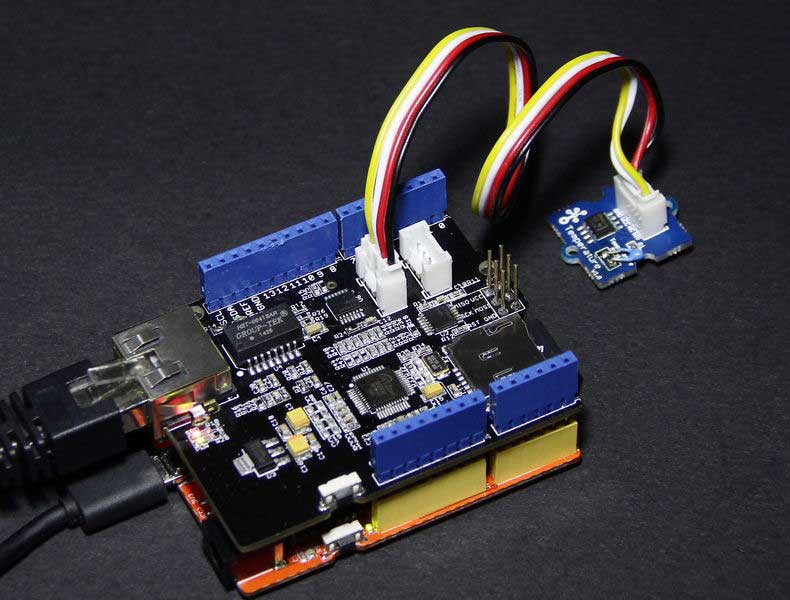
Part List : Seeeduino GPRS , Sim Card , Base Shield , Grove – Temperature
1. Mount Base Shield to your Seeeduino GPRS and connect Grove – Temperature to A5.
2. Connect Arduino to PC via USB cable;
Software
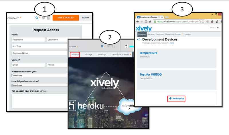
1. If you haven’t an account,you should Register an account in xively and login.
2. Now,we can click Develop to add a device.
3. Download the library:Seeeduino GPRS Library.
4. Unzip and put it in the libraries file of Arduino IDE by the path: ..\arduino-1.0.1\libraries.
5. Restart the Arduino IDE.
6. Open the example “GPRS_ConnectTCP” via the path: File –> Examples –> Seeeduino_GPRS_master –> GPRS_ConnectTCP. you need to modify some parameters.
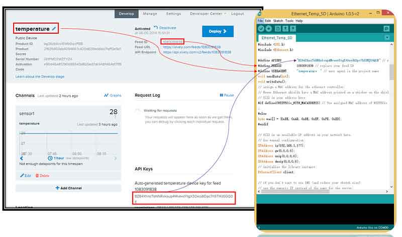
7. Upload the program to Arduino. If you do not know how to upload code, please click [here],please pay attention to that driver of Seeeduino GPRS is Leonardo.
Results
Now,we will show result.
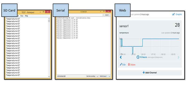
1. Open Serial Monitor,you will see some temperature information.
2. What’s more, we can see information from web.
Is it very easy ? you can begin your project.
FM Radio Function
Seeeduino GPRS has a FM radio function. Open the example sketch FM_Test in libraries/Seeeduino_GPRS/example/FM_Test/, and connect a button to your board, then compile the sketch and upload it to your board, Seeeduino GPRS functions like an FM radio. Even the channel can be changed with the button.
#include <fm.h>
#include <SoftwareSerial.h>

int channelButton = 5; //used for changing channel
FM fm;

void setup() {
    pinMode(channelButton,INPUT);
    Serial.begin(9600);
    Serial.println("FM Test...");
    fm.preInit();
    while(0 != fm.powerOn()){
        Serial.println("FM power on failed, try again...");
        delay(2000);
    }
    fm.setVolume(6); //0,1,2,3,4,5,6
    fm.scanChannel();
    Serial.println("FM init success");
}

void loop() {
    while(HIGH == digitalRead(channelButton)){
        delay(50);
    }
    Serial.print("change Channel\r\n");
    fm.channelNext();
    while(LOW == digitalRead(channelButton)){
        delay(50);
    }
}
Bluetooth Function
Seeeduino GPRS can be used as a bluetooth device, but it is still not very stable yet. There are two examples sketches in library. The first one is Bluetooth AT Command, you can send AT command to Seeeduino GPRS through it, and the other one is Bluetooth_Communicate, you can communicate with Seeeduino GPRS in SPP profile with it, but it may go wrong while connecting to your bluetooth device or mobile. Below is the code of Bluetooth AT Command
#include <bluetooth.h>
#include <SoftwareSerial.h>

#define DEFAULT_TIMEOUT 5
#define BT_BUF_LEN      32
BlueTooth bluetooth;

char bluetoothBuffer[BT_BUF_LEN];
int start = 0;

void setup() {
    Serial.begin(9600);
    Serial.println("Bluetooth AT Command Test...");
    bluetooth.preInit();
    delay(3*1000);
    while(0 != bluetooth.powerOn()){ //bluetooth PowerOn
        Serial.println("bluetooth power on failed, try again...");
        delay(2000);
    }
}

void loop() {
    if(bluetooth.serialSIM800.available()) {
        start = 1;
    }else{
        delay(500);
    }

    if(start




دیدگاهها
هیچ دیدگاهی برای این محصول نوشته نشده است.